Peripherals interfaced to the system via channels. A channel was a specialized processor with the instruction set optimized for transferring data between a peripheral and main memory. In modern terms, this could be compared to direct memory access (DMA).
There were initially two types of channels; byte-multiplexer channels, for connecting "slow speed" devices such as card readers and punches, line printers, and communications controllers, and selector channels for connecting high speed devices, such as disk drives, tape drives, data cells and drums. Every S/360 (except for the Model 20, which was not a standard S/360) had a byte-multiplexer channel and 1 or more selector channels. The smaller models (up to the model 50) had integrated channels, while for the larger models (model 65 and above) the channels were large separate units in separate cabinets, such as the IBM 2860 and 2870.
The byte-multiplexer channel was able to handle I/O to/from several devices simultaneously at the device's highest rated speeds, hence the name, as it multiplexed I/O from those devices onto a single data path to main memory. Devices connected to a byte-multiplexer channel were configured to operate in 1-byte, 2-byte, 4-byte, or "burst" mode. The larger "blocks" of data were used to handle progressively faster devices. For example, a 2501 card reader operating at 600 cards per minute would be in 1-byte mode, while a 1403-N1 printer would be in burst mode. Also, the byte-multiplexer channel had an optional sub-selector section that would accommodate tape drives. The byte-multiplexor's channel address was typically "0" and the sub-selector addresses were from "C0" to "FF." Thus, tape drives on S/360 were commonly addressed at 0C0-0C7. Other common byte-multiplexer addresses were: 00A: 2501 Card Reader, 00C/00D: 2540 Reader/Punch, 00E/00F: 1403-N1 Printers, 010-013: 3211 Printers, 020-0BF: 2701/2703 Telecommunications Units. These addresses are still commonly used in z/VM virtual machines.
The S/360 models 30, 40, and 50 had an integrated 1052-7 console that was usually addressed as 01F, however, this was not connected to the byte-multiplexer channel, but rather, had a direct internal connection to the mainframe.
Selector channels enabled I/O to high speed devices. These storage devices were attached to a control unit and then to the channel. The control unit enabled clusters of devices to be attached to the channels. On higher speed S/360 models, multiple selector channels, which could operate simultaneously or in parallel, improved overall performance.
Control units were connected to the channels with gray "bus and tag" cable pairs. The bus cables carried the address and data information and the tag cables identified what data was on the bus. The general configuration of a channel was to connect the devices in a chain, like this: Mainframe—Control Unit X—Control Unit Y—Control Unit Z. Each control unit was assigned a "capture range" of addresses that it serviced. For example, control unit X might capture addresses 40-4F, control unit Y: C0-DF, and control unit Z: 80-9F. The capture ranges had to be a multiple of 8, 16, 32, 64, or 128 devices and be aligned on appropriate boundaries. Each control unit in turn had one or more devices attached to it. For example, you could have control unit Y with 6 disks, that would be addressed as C0-C5.
The cable ordering of the control units on the channel was also significant. Each control unit was "strapped" as High or Low priority. When a device selection was sent out on a mainframe's channel, the selection was sent from X->Y->Z->Y->X. If the control unit was "high" then the selection was checked in the outbound direction, if "low" then the inbound direction. Thus, control unit X was either 1st or 5th, Y was either 2nd or 4th, and Z was 3rd in line. It was also possible to have multiple channels attached to a control unit from the same or multiple mainframes, thus providing a rich high-performance, multiple-access, and backup capability.
Typically the total cable length of a channel was limited to 200 feet, less being preferred. Each control unit accounted for about 10 "feet" of the 200-foot limit.
Block multiplexer channel
IBM introduced a new type of I/O channel on the 360/85 and 360/195: the 2880 block multiplexer channel. The channel allowed a device to suspend a channel program, pending the completion of an I/O operation and thus to free the channel for use by another device. The initial use for this was the 2305 fixed-head disk, which had 8 "exposures" (alias addresses) and rotational position sensing (RPS).
These channels could support either standard 1.5 MB/second connections or, with the 2-byte interface feature, 3 MB/second; the later used one tag cable and two bus cables.
Basic hardware components
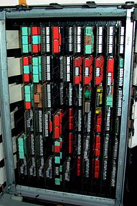
Being somewhat uncertain of the reliability and availability of the then new monolithic integrated circuits, IBM chose instead to design custom hybrid integrated circuits using discrete flip chip mounted glass encapsulated transistors and diodes with silk screened resistors on a ceramic substrate, then either encapsulated in plastic or covered with a metal lid. Several of these were then mounted on a small multi-layer printed circuit board to make a "Solid Logic Technology" (SLT) module. Each SLT module had a socket on one edge that plugged into pins on the computer's backplane (the reverse of how most other company's modules were mounted).


0 comments:
Post a Comment